Temperature swings define the UAE’s operating environment. Summer readings climb past 48°C, while desert and mountain zones can drop close to freezing overnight. That swing puts real stress on pipelines, storage tanks, and process equipment across Abu Dhabi, Dubai, Sharjah, and Ras Al Khaimah — which is why heat trace cables sit at the center of so many industrial designs in the region.
Oil and gas alone accounts for over 30% of UAE GDP, and its pipeline network stretches across desert, coastline, and industrial zones carrying oil, gas, chemicals, and water every day. When a pipeline loses temperature, the fluid inside thickens, flow rates drop, pressure builds, and equipment takes the strain — all of which eventually shows up as downtime and repair cost. Refineries, desalination plants, power stations, and chemical facilities all build heat trace into their design for exactly this reason.
The scale of adoption: More than 30,000 heat trace systems went into service across the UAE and wider Gulf in 2025 alone, protecting pipes and equipment from both freeze and heat-related failure. In Dubai and Abu Dhabi, sites running properly specified systems saw weather-related downtime drop by roughly 27%.
What Is a Heat Trace Cable?
A heat trace cable is an electric heating element run along a pipe, tank, or valve and held in place under insulation. Current passing through the cable generates heat, which transfers directly into the surface it’s tracing, holding the process temperature where it needs to be.
Facilities rely on this heat for a few specific jobs: stopping water and chemicals from freezing, keeping viscous fluids like crude oil moving, preventing thickening in cold conditions, and generally shielding pipework from temperature-related damage. That’s why the technology shows up so consistently across oil and gas sites, chemical plants, power generation, and water treatment.
How the Heating Process Works
The mechanism is electrical resistance: current meets resistance inside the cable core, and that resistance converts into heat. The cable sits in direct contact with the pipe surface, so heat moves from cable to pipe as the assembly warms. A layer of insulation over the top holds that heat in place rather than letting it escape to the surrounding air.
A working system needs five things in place together: the heating cable itself, a power feed, a temperature sensor, a controller or thermostat, and thermal insulation. The sensor reports pipe or surface temperature back to the controller, which switches the cable on or off to hold the target range. Most UAE industrial installations now run automated controls that respond to shifting ambient conditions on their own, which helps on both the safety and the energy-efficiency side.
For a step-by-step breakdown of sizing and selecting a system — including a full selection checklist — see how heat trace cables work in practice.
Cable Types
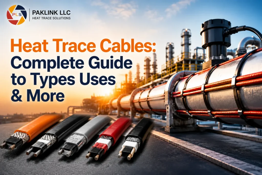
Four cable families cover most industrial heat trace applications, and each one fits a different operating profile. For the deepest technical comparison — including skin-effect cable for very long runs — see the full guide to heat trace cable types.
Self-Regulating Cable
Self-regulating cable adjusts its own output as ambient temperature shifts — it draws more power over colder sections and backs off where the pipe is already warm. That behavior reduces overheating risk automatically, cuts energy draw compared to fixed-output cable, and makes it a common choice for outdoor pipelines where conditions vary along the run. It’s also generally considered safer on plastic piping, and installation is relatively straightforward.
Constant Wattage Cable
Constant wattage cable holds a fixed output across its entire length regardless of ambient conditions. That predictability suits long pipeline runs, stable continuous processes, and storage tank heating, where an external controller manages the on/off cycling rather than the cable itself.
Mineral-Insulated (MI) Cable
MI cable is built for the harshest conditions — high continuous temperatures, chemical exposure, and moisture — using a metal sheath and mineral fill construction. That toughness is why it’s the standard choice inside oil refineries and petrochemical plants, and in hazardous-area zones generally.
Series Resistance Cable
Series cable delivers a fixed heat output along its length, independent of temperature — similar in that sense to constant wattage cable, but built on simpler series-resistance construction. For applications with predictable, steady heating needs, it’s a dependable, low-cost option that holds up well in harsh environments and pairs easily with standard insulation.
Cable Types at a Glance
| Attribute | Self-Regulating | Constant Wattage | Mineral Insulated (MI) | Series Resistance |
|---|---|---|---|---|
| Output behavior | Adjusts with temperature | Fixed wattage per length | Fixed, built for extremes | Fixed; heat varies with applied voltage |
| Max circuit length | Long, power-limited | Moderate, voltage-drop-limited | Very long, high-temp rated | Short to moderate |
| Best fit | Freeze protection, variable exposure | Uniform maintenance heat | High-temperature, process-critical lines | Simple, low-cost short runs |
| Hazardous-area use | Yes, with approvals | Yes, with approvals | Strong fit — robust by design | Yes for some rated types |
| Lifecycle cost profile | Moderate | Moderate | Higher upfront, lower upkeep | Lower upfront, moderate upkeep |
Power Supply and Circuit Design
Getting the electrical design right matters as much as choosing the right cable family.
- Standard installations run on either 230V or 110V supply
- A 10–20A circuit typically supports up to around 80 meters of cable
- Split longer runs into roughly 60–80 meter sections to keep voltage drop under control
- Fit GFCI (ground-fault) protection on every circuit
- Size breakers and ground-fault protection to match the actual load
- Watch for voltage decline on long runs and split into parallel circuits where the load calls for it
- Stay inside the manufacturer’s maximum circuit-length limits
- Use certified terminations and junction boxes wherever the area classification requires them
- Label every circuit and keep wiring diagrams on site for future maintenance
If a proposed run looks too long for a single circuit, splitting it early avoids voltage-drop problems and makes servicing easier down the line.
Commissioning Checklist
Run through this sequence before a new heat trace system goes live:
- Visually inspect cables, insulation, and terminations
- Confirm the cable is securely fixed and undamaged
- Verify supply voltage and breaker sizing match the design
- Test ground-fault protection operation
- Run a continuity test on every circuit
- Perform and record an insulation resistance (megger) test
- Confirm sensor placement and wiring
- Check controller setpoints, alarms, and configuration
- Measure operating current against the design figure
- Run the system under real conditions and log temperatures
- Label circuits and file the test records for future reference
Where These Cables Get Used
For a broader look at industry-specific use cases, see top industrial applications of heat trace cables.
Industrial processing — oil and gas plants, chemical facilities, power stations, water treatment sites, and food production lines all depend on heat trace to keep operations running through temperature swings.
Freeze protection — exposed water lines, firewater loops, valves, and pumps are the most common freeze-protection targets during cooler UAE nights.
Process temperature control — viscous fluids like heavy fuel oil, bitumen, molasses, and various industrial chemicals need steady heat just to keep flowing; without it, they harden and block the line.
Commercial and infrastructure use — district cooling plants, desalination facilities, airport fuel systems, solar installations (clearing dew and frost off mirrors and piping to protect efficiency), and building services like roof gutters and drains (preventing ice-related blockages at height) all use heat trace in less obvious but equally important ways.
System Components
A complete heat trace system is built from several parts working together: the heating cable, power connection kits, end seals, sensors, control panels, and insulation. For a full breakdown of every component — including junction boxes, GFCIs, and splice/end-cap details — see our dedicated components guide.
Selecting the Right Cable
Selection quality directly determines system lifespan. The key factors are pipe material, pipe size, required heat output, ambient temperature range, hazardous-area classification, and available power supply — with fluid type usually driving the final decision.
Calculating Heat Loss
Heat loss is driven by pipe diameter, insulation thickness, wind exposure, and outdoor temperature. The standard formula is:
Q = U × A × ΔT
- Q = heat loss (watts, W)
- U = overall heat transfer coefficient (W/m²·K)
- A = surface area (m²)
- ΔT = temperature difference (°C or K)
Worked example, long pipeline: A 4-inch carbon steel pipe carrying heavy oil needs to hold 60°C so the oil keeps flowing. On a desert winter night, outside temperatures can fall to 5°C. Even with 50mm of insulation in place, some heat still escapes — and closing that gap typically calls for a cable rated around 35–45 W/m, depending on the exact pipe size, temperature spread, and insulation thickness.
Worked example, freeze protection: For a smaller freeze-protection case — holding a fluid at +20°C against an outside temperature of -20°C — the cable generally needs to supply somewhere around 10–15 W/ft to offset that heat loss. The right number always comes back to the specific heat loss for that pipe under its coldest design condition.
For a complete selection checklist with control-option comparisons, see how heat trace cables work — a practical guide.
Installing a Heat Trace System
Full installation guidance is covered separately — here’s the outline.
Before installation: inspect the pipe, clear away dirt and debris, confirm the power supply is ready, and make sure all approvals are in place.
During installation: run cables evenly, avoid sharp bends, fix cables using approved tape, and place sensors at their correct positions.
After installation: measure resistance, check the temperature response, and verify controller settings.
Common Installation Mistakes
These are the errors that most often lead to system failure, wasted energy, or safety issues:
- Overlapping cable — self-regulating cable shouldn’t cross itself unless the manufacturer specifically allows it; overlaps risk localized overheating and damage.
- Under-specified insulation — thin insulation lets heat escape, driving power consumption up without necessarily reaching target temperature.
- Poor sensor placement — a sensor in the wrong spot leads to inaccurate readings and either overheating or underheating.
- Sharp bends or handling damage — tight bends or rough installation can damage the heating core; stay within the minimum bend radius.
- Ignoring voltage drop — long runs lose effectiveness as voltage drops; split them into smaller loops where needed.
- Weak grounding — inadequate grounding and ground-fault protection turns the system into a safety hazard.
- Unapproved parts — junction boxes, end seals, and connection kits should always be manufacturer-approved; substitutes raise the risk of failure or fire.
Safety Standards and UAE Compliance
Heat trace installations in the UAE need to meet national and international requirements, including IEC standards, ATEX certification where the zone classification calls for it, local authority approval, and proper grounding throughout. Certified components meaningfully reduce risk exposure.
Operating and Maintaining the System
Routine checks — inspect insulation condition, check the cable itself, and test controller function on a regular schedule.
What typically fails — cable damage and sensor faults account for most system issues; catching them early prevents unplanned downtime.
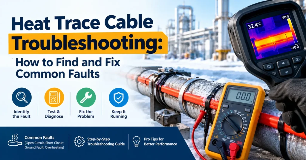
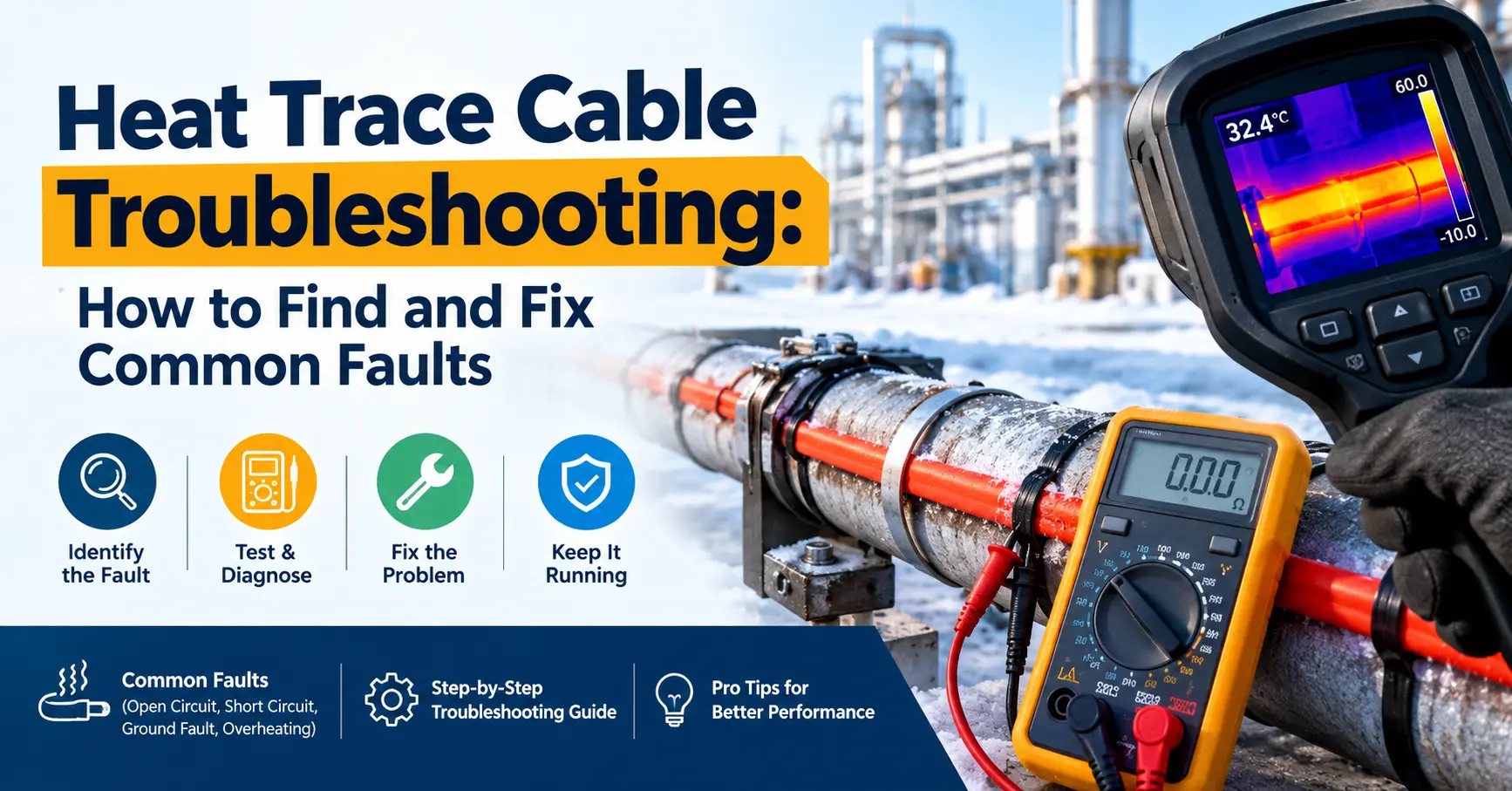
Troubleshooting guide:
- Open circuit — check continuity and all terminations
- Short to ground — isolate the circuit and run a megger test
- Damaged jacket — repair or replace the affected section
- Controller failure — swap in a spare unit and retest
Working safely in hazardous zones — follow local and international codes, use only certified hazardous-area components, apply ground-fault protection and lockout/tagout during any work, and follow manufacturer instructions on terminations throughout.
What Heat Trace Delivers
Operational value — steadier flow, fewer shutdowns, and better-protected assets across the site.
Cost value — lower repair bills, reduced energy spend, and longer equipment life over time.
Lifecycle Cost and Energy Efficiency
The real cost of a heat trace system isn’t the purchase price alone — it’s purchase cost plus energy use plus maintenance plus service life, added up over years of operation.
Upfront cost — self-regulating and series cables tend to cost less to buy initially. MI cable costs more upfront, reflecting its build for high-temperature, high-durability applications.
Running cost — driven by cable wattage per meter, pipe length, insulation quality, and outdoor temperature. Better insulation cuts monthly power draw directly. Self-regulating cable adds a further advantage here, since it naturally reduces output as temperatures rise — useful in a region with as much weather variability as the UAE.
Maintenance cost — a properly installed system needs less ongoing attention; damaged cable, weak terminations, and poor insulation are what drive maintenance costs up. MI cable, despite the higher initial spend, typically needs less upkeep over its service life.
Long-run value — over a 10–20 year horizon, a well-specified system with the right insulation and installation quality usually costs less overall than a cheaper system that needs more frequent attention.
Conclusion
Heat trace cable is a core part of safe, reliable industrial operation across the UAE — regulating temperature, protecting pipelines, and cutting the downtime that comes with weather-driven failures. Oil and gas plants, power stations, and desalination facilities all rely on it daily. Getting the cable choice, installation quality, and inspection schedule right is what keeps that value showing up over the long term in a demanding climate. If you’re planning a heat tracing system for a site in Abu Dhabi, Dubai, or elsewhere in the Gulf, our engineers handle design, sizing, installation, and ongoing maintenance for certified systems across oil, gas, and desalination applications.
Frequently Asked Questions
How do I know which cable type fits my application?
Match the cable to your specific conditions: self-regulating for variable ambient temperatures and freeze protection, constant wattage for long uniform runs, MI cable for high-temperature or hazardous-area work, and series cable for simple, predictable, low-cost installations.
What’s the difference between freeze protection and process temperature maintenance?
Freeze protection keeps a fluid above freezing during cold exposure — typically a lower, less demanding target. Process temperature maintenance holds a specific operating temperature (often well above ambient) so a viscous fluid keeps flowing correctly; it usually needs a more carefully calculated wattage.
Can heat trace cable be installed on plastic pipe?
Yes, self-regulating cable in particular is commonly used on plastic piping, since it doesn’t produce the fixed high output that could damage the pipe material.
How long does a heat trace system typically last?
Service life depends heavily on cable type and installation quality. MI cable, properly installed, often outlasts self-regulating or series cable by a wide margin, though it comes with a higher initial cost.
Does the UAE require certification for heat trace systems in hazardous areas?
Yes — installations in classified hazardous areas need ATEX-certified components and must follow IEC standards, along with proper grounding and approved terminations throughout.
What causes most heat trace system failures in the field?
Cable damage from installation handling and sensor placement errors are the two most common root causes, followed by inadequate insulation and voltage drop on oversized circuit runs.