
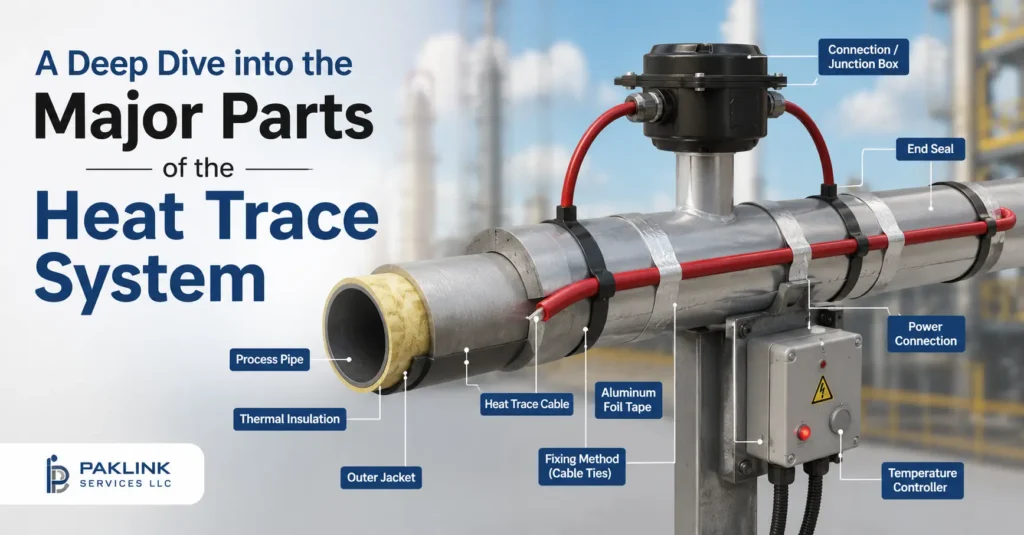
A heat trace system rarely fails because the cable itself gave out. More often it’s a connection point, a missed ground-fault threshold, or insulation that was closed up before anyone confirmed the wiring underneath was sound. Understanding what each component does — and which standard governs it — is what separates a system that just gets installed from one that keeps working for its full service life.
This walks through the system the way power actually moves through it: from the connection that brings electricity in, through the cable and its terminations, into the controls and protection that keep it safe, and finally through the testing that has to happen before anything gets buried under insulation.
For a full guide to sizing and selecting the cable itself, see our complete guide to heat trace cables and our comparison of major cable types.
Exploring the Major Parts of the Heat Trace System
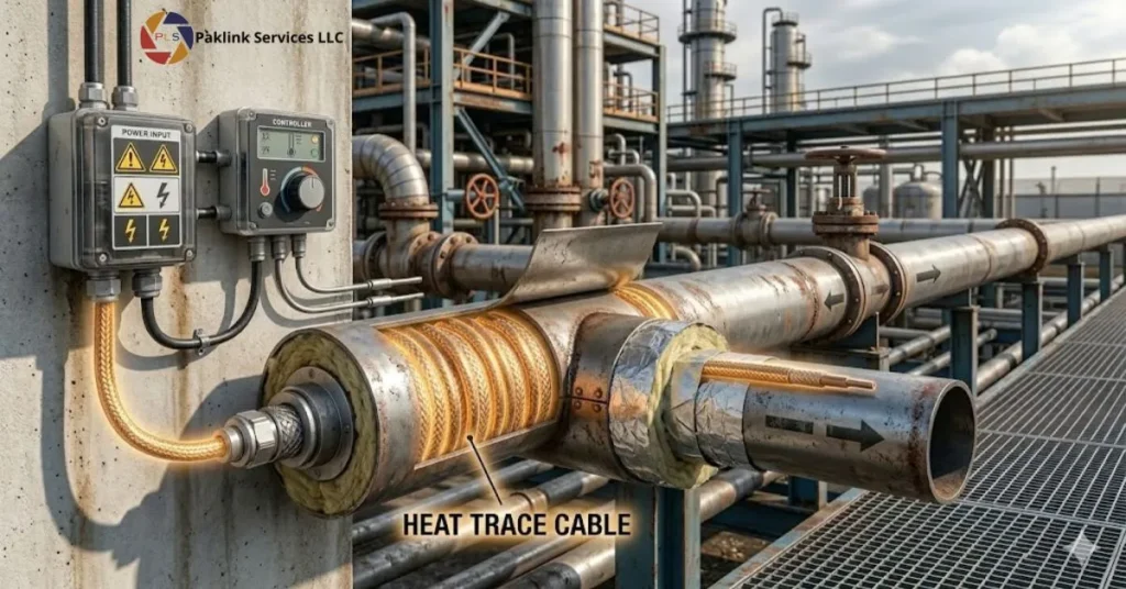
1. Power Connection Kits for Heat Trace Cable
Every circuit starts here — the point where facility power actually joins the heating cable. This is a genuinely different component from an end seal or a splice kit, even though all three often get lumped together as “termination hardware”:
- Power connection kits join the cable to the electrical supply, typically inside a junction box, and are rated for either a single circuit or multiple circuits depending on the kit
- End seal kits close off the far end of a heating cable run, keeping moisture out of the core — some versions include an indicator light that confirms power is actually reaching the far end of the circuit
- Splice and tee kits join two lengths of cable together, or branch a single circuit into two directions
Every power connection, splice, and end seal needs roughly 12 to 18 inches of extra cable to work with — that length accounts for stripping the cable back for termination and leaves slack for future repairs without cutting into the circuit’s design length. The same logic applies at every valve, flange, and pump support along the route.
2. Temperature Sensors for Heat Trace Circuits
A temperature sensor — usually placed on the pipe itself, under the insulation, away from anything that would skew the reading — feeds data back to a controller, which switches the circuit on or off to hold a target temperature. Sensor placement matters as much as sensor quality: a poorly placed sensor gives inaccurate readings regardless of how good the hardware is.
3. Control Panels for Heat Trace Systems
The controller uses sensor data to decide when to power the cable, and it can manage this for a single circuit or, on larger sites, many circuits at once through a networked panel. Networked panels monitor multiple circuits from one interface, log temperature trends over time, and flag a failing circuit before it becomes a failed one — a real advantage as circuit count grows on larger sites.
4. Ground-Fault Equipment Protection for Heat Trace Circuits
This is the component most often under-specified, and it works differently than most people expect. Electric heat tracing falls under NEC Article 427, and Section 427.22 specifically requires ground-fault protection of equipment (GFEP) on branch circuits supplying heat tracing — with a narrow exception for critical processes, where an alarm is required instead of an automatic trip. Canadian installations follow the equivalent requirement under CSA C22.1-21, Rule 62-116.
The distinction that trips people up: personnel-protection GFCIs (like a bathroom outlet) trip at roughly 4 to 6 milliamps. Equipment-protection GFEP for heat tracing is set much higher, typically 6 to 50 milliamps, with 30 mA commonly used as the default — because heat tracing has some inherent leakage current in normal operation, and a personnel-level trip setting would nuisance-trip constantly.
5. Junction Boxes and Hazardous-Area Enclosures for Heat Trace
Junction boxes protect every connection point from moisture, dust, and physical damage. In classified hazardous areas, the box itself needs to carry the correct area-classification rating, not just be weatherproof — a standard-duty enclosure installed where an explosion-proof rated box was required is a common audit finding.
6. Insulation and Cladding Over Heat Trace Cable
Insulation isn’t just there to conserve energy — it’s the component that lets the cable’s rated output actually reach the pipe instead of dissipating into the air. Visible cable outside of power connection kits or end seals usually signals an insulation gap, and a small gap lets moisture in that degrades performance before it becomes visibly obvious.
7. Pre-Insulation Testing for Heat Trace Circuits
This step gets skipped more often than any other, usually under pressure from insulation contractors on-site — and it shouldn’t be, because a fault found after insulation is installed is far more expensive to fix than one found before. IEEE 515 sets the reference test procedure: connect a megohmmeter between the heating cable’s bus wires and its metallic braid, apply 2,500 Vdc for polymer-insulated cable or 1,000 Vdc for mineral-insulated cable. A result between 20 megohms and infinity is acceptable; below 20 megohms points to insulation damage that needs fixing before service. The same test should be repeated at a lower voltage (at least 500 Vdc) once the full installation is complete, immediately before thermal insulation goes on.
Putting It Together
None of these parts works in isolation. A correctly sized cable paired with an under-specified ground-fault device, or a well-chosen sensor location undermined by a skipped megger test, both end up as the same outcome: a system that looks complete on paper but fails in the field. The components matter less individually than they do as a chain — connection, control, protection, and verification, each one covering a failure mode the others don’t.
FAQs
What’s the difference between a GFCI and the ground-fault protection heat trace actually needs?
Household GFCI protection trips at 4–6 mA, calibrated to protect people from shock. Heat tracing uses ground-fault equipment protection (GFEP) instead, required under NEC 427.22, which trips in the 6–50 mA range (commonly set at 30 mA) — a threshold calibrated for equipment protection rather than personnel protection, since heat trace circuits carry some normal leakage current that would cause a personnel-rated GFCI to trip constantly.
How much extra cable should be planned for at each connection point?
Roughly 12 to 18 inches at every power connection, splice, and end seal, to allow for stripping and termination plus enough slack to replace the kit later without shortening the circuit’s designed length.
What voltage is used to megger-test a heat trace circuit before insulation goes on?
IEEE 515 specifies 2,500 Vdc for polymer-insulated cable and 1,000 Vdc for mineral-insulated cable, with an acceptable reading between 20 megohms and infinity.
Can a heat trace circuit stay energized if it develops a ground fault?
In most cases no — NEC 427.22 requires the circuit to disconnect. The exception is for critical processes where safely shutting down isn’t possible; those installations require an alarm instead of an automatic trip, but the fault still has to be addressed.
Why do end seal kits sometimes include a light?
A lighted end seal confirms that power is reaching the far end of the circuit — useful during commissioning to verify the full run is energized correctly, and useful later as a quick visual check without needing test equipment.
Is a standard junction box acceptable for hazardous-area heat trace installations?
No — hazardous-area installations require junction boxes and connection kits rated for that specific area classification, not general-purpose weatherproof enclosures. Confirm the required rating for the zone before specifying hardware.