Somewhere between a transmitter and a control room screen, a signal needs to become something a person can read standing at a panel. That’s the job of a process indicator — and it’s the single most-specified, least-explained instrument on most industrial panels. Datasheets assume you already know which type you need. This guide starts one step earlier: what a process indicator actually is, the main types on the market, and how to pick between them before you ever open a product page.
What Is a Process Indicator?
A process indicator is a panel-mount device that takes an analog signal from a transmitter or sensor — current, voltage, or a sensor-specific input like RTD or thermocouple — and displays it in a form an operator can read directly: a number, a bar graph, or a color-coded state.
It is not a controller. A process indicator shows a value; it doesn’t run a control loop or make automated adjustments (some models add a simple threshold output for an alarm or relay trigger, but that’s a secondary feature, not the core function). It’s also not a data logger — indicators show the present value in real time; they generally don’t store history unless the model is specifically built for that.
The core job stays constant across every type: take a raw signal, make it legible, put it where a human is standing.
The Main Types of Process Indicators
Numeric / Digital Display Indicators
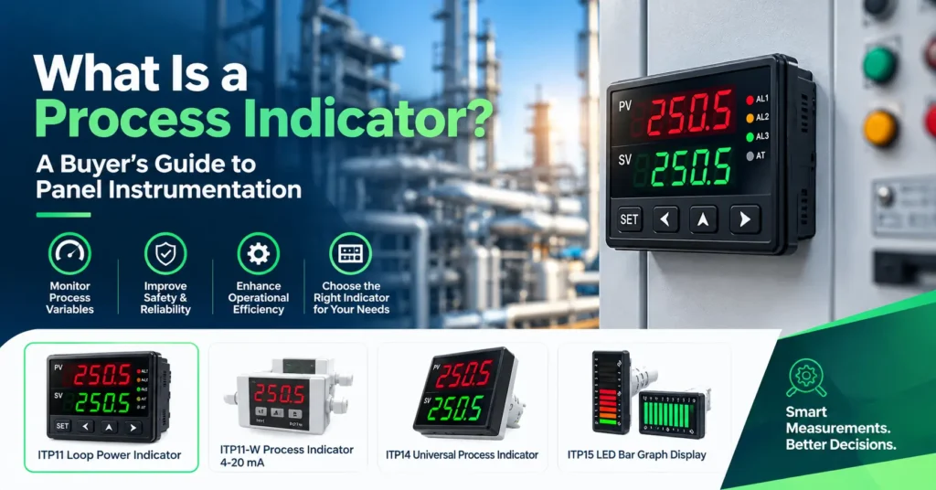
Show the process value as a number — e.g., “42.6 bar” — usually on a 7-segment LED display. Best when the operator needs the actual value, not just a range position. The AKYTEC ITP14 and ITP11 are examples of this format.
Bar Graph Indicators
Show the process value as a row of LEDs that fill in proportionally — read as a position, not a number. Faster to scan across a bank of loops, at the cost of precision. The AKYTEC ITP15 is this format — see the full ITP15 breakdown for how its 10-bar, two-colour display works.
Universal Indicators
Accept multiple input types — current, voltage, RTD, thermocouple — on the same physical unit, configured at setup rather than fixed at manufacture. Useful when a project has mixed signal types across a panel and standardizing on one part number reduces spares complexity. The AKYTEC ITP17 covers this category — read the ITP17 guide for the full input-type breakdown.
Loop-Powered Indicators
Draw their own operating power from the 4–20 mA current loop they’re measuring, instead of needing a separate power feed. This removes a wiring run per indicator, which matters when a panel is carrying a dozen or more loops. The AKYTEC ITP11 guide covers loop-powered wiring and specs in depth.
How to Choose Between Them
Work through these three questions in order — they eliminate most of the field before you look at a single datasheet.
1. Do you need a value, or a status? If the operator needs to read “how much” — an actual pressure, temperature, or flow figure — a numeric indicator is the right format. If they only need to read “how full” or “is this in range” at a glance, a bar graph does that faster.
2. Is auxiliary power available at the mounting point? If there’s a spare 24V DC feed already at the panel, power source isn’t a constraint. If the indicator is going into a tight cabinet or a remote spot with no spare wiring budget, a loop-powered model removes that requirement entirely.
3. Is the signal type fixed, or will it vary across the project? A single, known signal type (say, every loop on the panel is 4–20 mA) doesn’t need a universal indicator — a dedicated model is usually simpler and cheaper. A project with mixed current, voltage, and temperature-sensor inputs benefits from standardizing on one universal part number instead of stocking three different indicator types.
Comparison at a Glance
| Type | Reads as | Power | Best fit |
|---|---|---|---|
| Numeric (ITP14) | Exact value | Auxiliary | Operator needs the real number |
| Bar graph (ITP15) | Range position | Auxiliary | Fast scan across many loops |
| Universal (ITP17) | Value, multi-input | Auxiliary | Mixed signal types on one project |
| Loop-powered (ITP11) | Exact value | Signal loop itself | No spare power wiring, tight panel space |
Where Process Indicators Fit on a Panel
They sit downstream of the transmitter and upstream (or alongside) the controller/PLC — a parallel tap on the signal, not a link in the control chain. That’s what makes them safe to add or remove without touching the control logic: pulling a display off a loop doesn’t break the loop. This is why they show up across so many unrelated applications — water pump stations, thermal processing panels, energy-management cabinets, oil & gas field panels — the display’s job is identical even when the process behind it isn’t.
Specifying for a GCC Panel
For projects across the UAE, Qatar, Saudi Arabia, and the wider GCC, Paklink’s instrument and control team can confirm signal type, power method, and mounting format before you commit to a part number — see the full industrial process display range or get a quote for your panel.