
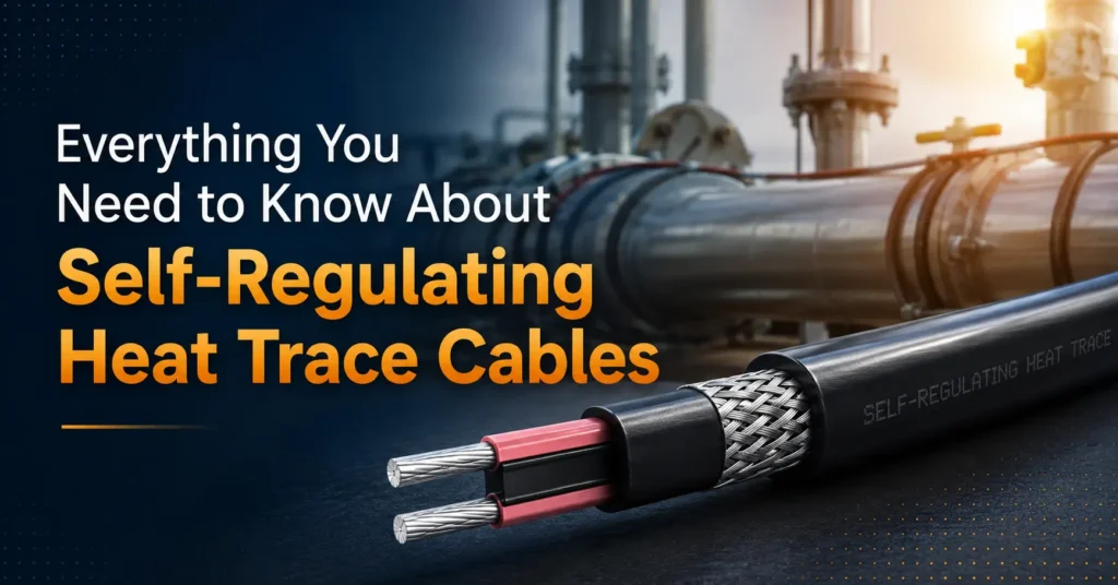
Self-regulating heat trace cables are heating elements placed along pipes and equipment that vary their own electrical resistance as temperature changes. The cable delivers more power to cold spots and less to warm spots, so every section of a pipe run stays at the target temperature without a separate external controller managing each zone. For a comparison against other cable families — constant wattage, mineral-insulated, and series resistance — see our complete guide to heat trace cable types.
The UAE runs a large number of oil and gas, industrial, and high-end construction projects that need constant fluid and equipment temperatures maintained — and self-regulating cable is one of the most common tools for doing that reliably. Using it well can lower energy spend, cut the risk of frozen or burst pipes, and shorten commissioning time on remote or coastal facilities.
How Self-Regulating Cable Works
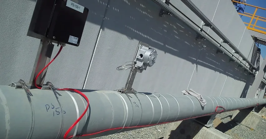
The core principle: a special polymer inside the cable changes how much electricity passes through it as temperature moves up or down. Cold sections draw more current and heat up; warm sections resist current and put out less heat. The cable reacts point by point along its entire length, which means it’s essentially running its own thermostat at every inch of the run.
A practical example: when wind chills an exposed section of pipe, the cable there heats harder to keep the fluid flowing. Where the same pipe runs through a warm room, the cable backs off its output and saves power — keeping the whole system efficient without anyone adjusting anything manually.
Key Benefits
Energy savings and safe operation. The cable puts out heat only where the pipe actually needs it, which cuts wasted energy and lowers electric bills compared with a fixed-output system running at full power the entire time. The self-limiting design also prevents hot spots, which lowers fire risk from overheated surfaces.
Fit, flexibility, and reliability. Field teams can cut most self-regulating cables to length and, within manufacturer limits, overlap runs where the pipe layout requires it. That flexibility handles mixed exposures and long routes without adding maintenance headaches, and — because the cable resists runaway heat by design — overlapping generally doesn’t create the hot-spot risk it would with fixed-wattage cable.
Quick Decision Guide: Self-Regulating vs. Constant Wattage
|
Attribute |
Self-regulating cable |
Constant wattage cable |
|---|---|---|
|
Overheat risk |
Low — output drops as it warms |
Higher — needs careful spacing |
|
Cut to length in the field |
Yes |
No — factory length fixed |
|
Energy behavior |
Adjusts dynamically to conditions |
Fixed output regardless of conditions |
|
Best fit |
Freeze protection, long runs, variable exposure |
Short, uniform runs with stable conditions |
Where to Use Self-Regulating Cable
Oil, gas, and petrochemical. Plants place self-regulating cable on export lines, sampling lines, and tank piping to stop wax buildup and hydrate formation that can block flow — keeping product viscosity stable and avoiding costly process stops.
Building and commercial. Domestic water lines in cold rooms, specialty rooftop drains, and heated floor systems all use steady, gentle heat that protects both pipes and finishes without adding complex control wiring. For freeze-protection specifics on residential and small-commercial pipe runs, see our guide to protecting pipes with self-regulating cable.
Utilities and water treatment. Fire-protection piping during shutdowns and temporary skids at remote sites both benefit from tracing that prevents blockages and cuts the risk of emergency repairs on systems that need to stay ready.
Cable Types and Material Choices
Jacket and shield options. Choose PVC, fluoropolymer, or mineral-filled jacket compounds based on the site’s UV, chemical, and marine exposure. Add a metallic overshield where mechanical protection or EMI screening is needed, and match the jacket to the local environment rather than defaulting to a single spec across every run.
Temperature ratings. Pick a continuous temperature rating that matches the hottest expected service condition on that specific run. Many products handle continuous operation up to around 205°C for hot process lines, while lower-rated variants are built specifically for freeze protection at more moderate temperatures.
Design Steps for UAE Projects
Getting cable power right starts with the pipe itself, not a generic wattage figure. Base the watts-per-meter figure on three things together: how wide the pipe is, how thick the insulation will be, and what temperature the run needs to hold. A section running exposed to open air or wrapped in thin insulation needs more wattage than a well-insulated section carrying the exact same fluid — treating every meter of a run the same way is a common source of wasted energy on otherwise well-designed systems.
Heat-loss calculation, step by step:
- Fix the target pipe temperature, and separately note the coldest ambient temperature the site is likely to see
- Record the insulation type being used along with its thermal conductivity rating
- Use those figures to work out heat loss per meter, then build in a safety margin rather than sizing to the exact calculated minimum
- Choose a cable wattage that comfortably covers that heat-loss figure, and keep the full calculation on file as part of the project’s design documentation
Worked example — a 2-inch steel pipe at -20°C: Pull the pipe diameter and the insulation’s R-value into the heat-loss formula at that ambient temperature. Rather than estimating a wattage, cross-check the result against the manufacturer’s published wattage tables and pick a cable that matches or slightly exceeds what the calculation shows. Keep the circuit length within whatever limit the manufacturer specifies for that cable, and size the breaker to match. Mount the thermostat directly against the pipe surface — air-temperature sensing gives a misleading reading here — and set it to the actual pipe temperature the process requires, not a rounded estimate.
Installing the System
For a full step-by-step installation walkthrough, see our heat trace cable installation guide. What follows is the sequence specific to self-regulating cable.
Before the crew arrives on site. Confirm the site’s available voltage, check the maximum circuit length the chosen cable supports, and make sure every accessory kit needed is already on hand — running out of an end seal or splice kit mid-installation is a common, avoidable delay. Ground-fault protection and UAE electrical regulations should be built into the plan from day one, not treated as a box to tick at the end.
On site, in sequence:
- Strip away loose paint, rust, and scale from the pipe surface so tape and kits actually bond properly
- Run the cable along the pipe at the pitch the manufacturer recommends, keeping clear of tight bends that stress the core
- Secure the cable using tape or clips rated for the run’s operating temperature — a clip rated for the wrong temperature range will fail well before the cable does
- Fit end seals and splices using kits certified for that specific cable type, following the wiring diagram rather than improvising
- Test continuity and insulation resistance with a megger before anything gets covered, and save every reading to the project file
- Add thermal insulation over the finished run, label each circuit clearly, and put together a handover pack containing test results and warranty paperwork
Controls, Protection, and Monitoring
Control options. Add thermostats where the system needs tight temperature control or energy savings beyond what the cable’s self-regulating behavior already provides. Timers and remote alarms on critical lines get staff fast alerts before a developing fault turns into damage.
Protection devices. Ground-fault protection belongs on every circuit, with breakers sized to handle both startup and steady-state current. Local sensors paired with remote monitoring catch faults early and cut downtime.
Maintenance and Service Life
Regular checks. Inspect jackets, terminations, and supports after any structural work on the site, or on a six-to-twelve-month cycle otherwise. Re-run insulation-resistance testing after any repair and log every result — that record becomes the baseline for future troubleshooting and supports warranty claims.
Typical service life. With routine maintenance, installations commonly run 15–25 years. Replace damaged components promptly with certified splices and end seals so the rest of the system stays in service without an unplanned full replacement.
Safety and Regulatory Compliance
Hazardous-area approvals. Use products carrying ATEX or IECEx ratings for explosive or hazardous environments, and follow the manufacturer’s wiring and grounding steps completely rather than partially. Reputable brands that have passed independent inspections give an added layer of assurance during safety reviews.
On-site safety steps. Lock out and de-energize circuits before any termination or repair work, and keep written isolation steps on hand for maintenance crews. Training staff on heat-trace-specific hazards and safe testing methods reduces accidents and keeps the site aligned with its safety plan.
Common Mistakes to Avoid
Picking the wrong cable type. Don’t choose on price alone — match the cable to the job. Use self-regulating types where variable output and overlap genuinely help, and pick constant-wattage types where uniform heat across the entire run matters more than adaptability.
Cutting corners on terminations. Most field failures trace back to bad terminations. Use only approved kits, follow torque and sealing instructions exactly, and test every termination before insulation goes on — catching an issue here avoids a much costlier repeat site visit later.
Clearing Up Common Misconceptions
A few misunderstandings come up often enough to be worth addressing directly:
“They cost too much.” The upfront cost is genuinely higher than basic heat tape, but the energy savings from self-regulating behavior and the reduced maintenance over a multi-year service life typically offset that difference well before the system needs replacing.
“They overheat if the cable overlaps itself.” This is the opposite of how the technology works — the self-limiting design specifically reduces output as a section warms, which is what makes limited overlap tolerable in the first place. Manufacturer overlap limits still apply and should be followed.
“They’re hard to install.” Most self-regulating cable is designed for field cutting and straightforward termination. Installation still requires trained personnel for hazardous-area work and larger industrial systems, but it doesn’t demand the custom factory fabrication that older cable technologies needed.
Cost Savings and ROI
Self-regulating cable cuts power where heat isn’t needed and adds it only where the pipe is actually losing temperature. That local control lowers energy use on mixed-exposure runs and typically reduces maintenance costs compared with constant-wattage systems running at full output continuously.
Quick ROI calculation steps:
- Calculate heat loss per meter and multiply by run length to get total demand
- Estimate yearly run-hours based on local climate and process needs, then multiply by local electricity cost
- Compare that annual energy-plus-maintenance total against a constant-wattage alternative to find the payback period, factoring in expected service life and downtime savings
Where to Buy and Local Support
Buy from suppliers who keep stock in the UAE and can provide local design assistance and spare-parts delivery — local vendors materially speed up commissioning and cut downtime when issues come up. Paklink LLC stocks a full range of self regulating heating cables in the UAE, with in-house design support and local spare-parts availability for oil & gas, industrial, infrastructure, and marine projects across the Gulf.
When evaluating a supplier, ask for written design calculations, product datasheets, installation drawings, and clear warranty terms, and request references from similar regional projects.
FAQs
Will overlapping the cable cause overheating?
No — self-regulating cable reduces output as it warms, so overlap typically doesn’t create hot spots. Still follow the manufacturer’s specific overlap limits and protect the cable from mechanical strain during installation.
How long can a circuit run on one power feed?
Maximum length depends on the specific cable model and site voltage. Typical runs range from tens to several hundred meters — check the product datasheet and plan circuits against those figures rather than assuming a standard length.
What temperatures can the cables handle?
Many products operate continuously up to around 205°C, with some rated for higher short-term exposure. Check both continuous and short-term limits in the datasheet for the specific cable being specified.
Can the cable touch itself or run near other power lines?
Most designs tolerate crossing and limited self-contact, but avoid rubbing, sharp bends, and close contact with unrelated power lines, since those conditions accelerate wear regardless of the cable’s self-limiting design.
What tests should run after installation?
Continuity checks, insulation-resistance testing, and power verification at representative points along the run. Store every reading with the project file for future maintenance reference and warranty support.
Does self-regulating cable need approvals for hazardous areas?
Yes, where the site’s zone classification requires it — use products carrying ATEX or IECEx certification and follow the manufacturer’s grounding and wiring instructions in full. Skipping partial steps to save time is one of the more common findings in post-installation safety audits.